This paper briefly describes the composition principle of the electrical fire monitoring system, and analyzes the design basis and related specifications of the electrical fire monitoring system in the application. Finally, through the introduction of Ankerui residual current electric fire monitoring system in Fengxian Luting International Building, the realization of the function of electric fire monitoring system and its significance are expounded.
Yang Junjun An Kerui Electric Co., Ltd. Shanghai Jiading
0 Overview

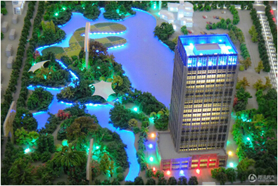
Fengxian Lvting International Building is located at 5088 Lane, Hangnan Road, Fengxian South Bridge (Hanyi Road Intersection). It is the chief ecological business model of Nanqiao Core Business District, with a 40-158 square meter 5A Grade A office building and the first choice for Fengxian New City Integrated Business Office. Sitting on nearly a thousand acres of ecological gardens and surrounding landscapes, creating a new field of Nanqiao ecological office. It is 400 meters away from Huancheng East Road and 600 meters away from the south bridge exit of S4 Hujin Expressway in the east. The future track No. 5 line is connected to the Hongqiao hub in the north, and the traffic advantage is outstanding.
The façade adopts granite and LOW-E double-layer insulating glass to present Art-Deco style; Nanqiao Commercial Office has a cutting-edge fresh air system, mechanical ventilation, low-carbon environmental protection; intelligent office system; the lobby is 9 meters high and has a bank inside. Business facilities such as supermarkets and cafes.
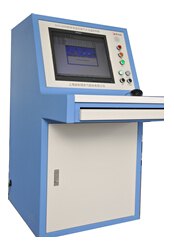
This project is 115 ARCM200BL-Z residual current fire detectors installed in the floor distribution box. The detector is connected to the Acrel-6000/Q piano electrical fire monitoring system of the control center through the bus.
1 reference standard
In recent years, in order to increase the intensity of electrical fire monitoring and prevention, the state has successively formulated or revised a number of relevant standards and regulations to strengthen the prevention of electrical fires. There are:
1.1. GB50045-95 (2005 edition) "Code for Fire Protection Design of High-rise Civil Buildings", which stipulates in Article 9.5.1 that a fire alarm system should be installed in places with high fire risk and dense personnel in high-rise buildings.
1.2. GB50016-2006 "Code for Fire Protection of Building Design", as specified in Article 11.2.7: The following places should be equipped with a residual current action electrical fire monitoring system. These venues include various types of theaters, galleries, warehouses, residential communities, hospitals, shops, schools, and more.
1.3. The relevant provisions of the national standard "Building electrical fire prevention requirements and testing methods" also clearly require that "the residual current action protector that automatically cuts off the power or alarm should be set at the power incoming end".
1.4. The products of the electrical fire monitoring system shall meet: GB14287.1-2005 "Electrical Fire Monitoring Equipment", GB14287.2-2005 "Residual Current Electric Fire Monitoring Detector", GB14287.3-2005 "Measurement Temperature Electric Fire Monitoring and Detection" 》
1.5. The installation and operation of the electrical fire monitoring system shall meet the requirements of GB13955-2005 "Installation and operation of residual current action protection device"
1.6. The power supply of the electrical fire monitoring system shall meet the requirements of GB50052 "Design Specifications for Power Supply and Distribution Systems"
1.7. The design of the electrical fire monitoring system shall meet the requirements of the Design Method of Electrical Fire Monitoring System (Interim Provisions)
2 system components
The electrical fire project of Fengxian Green Court International Building consists of electrical fire monitoring background, electrical fire detector and leakage current transformer.
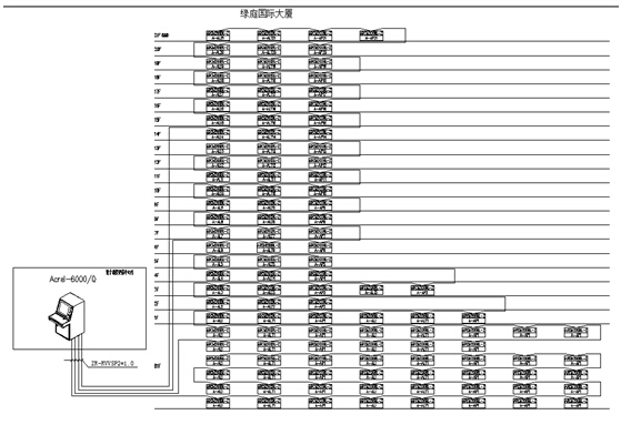
The project has 21 floors above ground and 1 underground. Among them, there are 25 fire detectors from 14 to 21 floors, one bus; 24 fire detectors from 6 to 13 layers, one bus; 34 underground fire detectors to 5 floors, one bus; There are 32 fire detectors in the rest of the layer, one bus; there are 4 communication buses. After the bus is connected in hand by hand, the bus is connected to the background of the console of the control center to form an electrical fire system. The leakage current transformer in the cabinet is connected to the leakage detector through the current line, and the leakage detector displays the leakage condition in real time. The above describes a set of electrical fire monitoring systems with stable signal and reliable accuracy. The system networking is divided into three layers:
1) Station management
The management of the station control management system for the electrical fire monitoring system is the direct window of human-computer interaction and the uppermost part of the system. Mainly composed of system software and necessary hardware devices, such as host, display, UPS power supply. The monitoring system software calculates, analyzes, and processes various types of data information on the site, and responds to the on-site transportation situation by means of graphics, digital display, sound, and indicator lights.
Monitoring host: used for data collection, processing, and data forwarding. Provides data interfaces for system management, maintenance, and analysis within and outside the system.
UPS: Ensure the normal power supply of the computer monitoring system, and ensure the normal operation of the station management management equipment when the whole system has power supply problems.
The background monitoring device is set in the control room.
2) Network communication layer
Communication medium: The system mainly adopts shielded twisted pair cable, realizes real-time communication between field device and host computer by RS485 interface and MODBUS communication protocol.
3) Field device layer
The field device layer is a data acquisition terminal, mainly for the ARCM200BL series of residual electrical fire monitoring detectors.
The system structure topology is as follows:

3 electrical fire equipment

3.1. Power supply
1 rated working voltage AC220V (AC175 ~ 245V)
2 Standby power supply: When the main power supply is under voltage or power failure, maintain the monitoring equipment working time ≥ 30 minutes
3.2. Work system
24-hour work schedule
3.3. Communication method
RS485 bus communication, Modbus-RTU communication protocol, transmission distance 1km, can extend the communication transmission distance through the repeater.
3.4. Monitoring capacity
1 The monitoring device can monitor up to 1024 monitoring units (detectors).
2 Can be equipped with ARCM series monitoring detectors.
3.5. Monitoring alarm items
1 Residual current fault (leakage): Fault unit attribute (part, type)
2 Temperature alarm (over temperature) : Fault unit attribute (part, type)
3 Current fault (overcurrent): Fault unit attribute (part, type)
Monitoring alarm response time: ≤30s
Monitoring alarm sound pressure level (A weighting): ≥70db/1m
Monitoring alarm light display: red LED indicator
Monitor alarm sound signal: Manually cancel, when the alarm signal is input again, it can be started again
3.6. Fault alarm item
1 The connection between the monitoring device and the detector is open and shorted.
2 main power undervoltage or power failure
3 standby power battery short circuit, open circuit
Fault alarm response time: ≤100s
Monitoring alarm sound pressure level (A weighting): ≥70db/1m
Monitor alarm light display: yellow LED indicator
Fault alarm sound signal: manual elimination, can be started again when there is alarm signal input again
The normal operation of the non-faulty loop is not affected during the fault
3.7. Control output
Alarm control output: normally open passive contact, capacity: AC250V 3A or DC30V 3A
3.8. Self-test items
1 Indicator check: alarm, fault, operation, main power, standby power indicator
2 monitor check
3 audio device inspection
Self-test time ≤60s
3.9. History
1 Record content: record type, time of occurrence, detector, area, fault description.
2 Record query: Query according to the date and type of the record.
3.10. Operational grading
1 Daily duty class: real-time status monitoring, history query.
2 Monitoring operation level: real-time status monitoring, history query, remote reset of detector.
3 system management level: real-time status monitoring, history query, remote reset of detectors, remote modification of detector parameters, monitoring equipment
System parameter setting and modification, operator addition and deletion.
3.11. Use of environmental conditions
1 Workplace: Fire control room, or installed side by side with fire control console
2 Working environment temperature: -10 ° C ~ +55 ° C
3 Working environment relative humidity: 5% ~ 95% RH
4 Altitude: ≤2500m
3.12, ARCM200BL series instruments
The ARCM200BL residual current electrical fire monitoring detector is designed for TT and TN systems below 0.4kV. It monitors and manages the fire risk parameters such as residual current, conductor temperature, overcurrent and overvoltage in the distribution circuit. Thereby preventing the occurrence of electrical fires and real-time monitoring of various power parameters, providing accurate data for energy management. The product adopts advanced microcontroller technology, with high integration, small size, convenient installation, intelligent, digital and networked. It is an ideal choice for building electrical fire prevention monitoring and system insulation aging prediction. The product complies with the standard requirements of GB14287.2-2005 "Electrical Fire Monitoring System Part 2: Residual Current Electrical Fire Monitoring Detector".
4 system function
4.1. Monitoring alarm function:
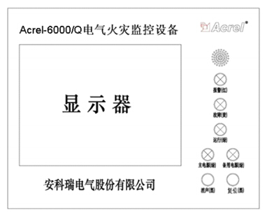
The monitoring equipment can receive the leakage and temperature information of multiple detectors, and emit an audible and visual alarm signal when the alarm occurs. At the same time, the red “alarm†indicator on the device lights up, the display indicates the alarm location and alarm type, and the alarm time is recorded. The sound and light alarm is always maintained. Until the display is reset by pressing the display "Reset" button. The audible alarm signal can also be manually removed using the display "Muffler" button.

Acrel-6000/Q piano desktop panel
4.2. Fault alarm function
Communication failure alarm: When a communication failure occurs between the monitoring device and any of the connected detectors, the corresponding detector in the monitoring screen displays a fault indication, and the yellow “fault†indicator on the device lights up, and a fault alarm sound is emitted. .
Power failure alarm: When the main power or backup power fails, the monitoring device also emits an audible and visual alarm signal and displays the fault information. You can enter the corresponding interface to view the detailed information and release the alarm sound. Hardware Business Network Information Center)http://news.chinawj.com.cn
Ultra Plantâ„¢ Grow Light offers One Chip Technology aimed to meet your indoor growing expectation such as improve plants' quality, increase yield, or better the margin, etc., all for helping you realize a higher return on your crops.
Ultra Plantâ„¢ Grow Light is combined our advanced All-In-One technology with patented optical design and customized light full spectrum supported from our experienced LED engineers, plant specialists and other partners working on horticulture.
From Ultra Plantâ„¢ APP, you are able to schedule the growing process including photoperiod, brightness and spectral in advance. The lighting system will help you grow smarter, easier and better.
Ultra Plantâ„¢ is the most versatile horticultural grow lighting fixture for indoor plants with flexible full spectrum, brightness control and uniform, wider light distribution, suitable for top lighting of all types of crops. No matter it applies to anywhere for any crop, Ultra Plantâ„¢ can do perfect work for you.
Grow Light For Vegetables,Vegetables Grow Lights,Improve Flower Quality Growth Lamp,Led Grow Lights For Growing Vegetables
Feton Corporation , https://www.ftplantled.com