Pay attention to the following requirements when designing the cutting mechanism of the start-stop crank flying shears:
1 The two cutting edge movements must be a closed curve of a certain trajectory. In the shearing engineering, the trajectory of the cutting edge is required to be smooth horizontally, and the horizontal dividing speed is a uniform linear shape, which is greater than or equal to the moving speed of the rolling stock.
2 When the maximum stress occurs during the cutting of the cutting edge, ensure that the crank that bears the load is safe.
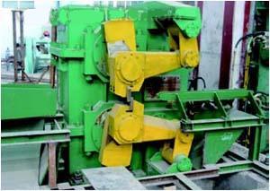
Figure 1 Flying shears physical picture
Traditional manual calculations first need to make a schematic diagram of the mechanism, apply the concepts of mechanical formulas and plane geometry, solve the results, and then draw the various curves required according to the results. Due to problems such as approximate rounding in calculation engineering, the result can only be used as a theoretical value. Therefore, the safety factor of the calculated result is usually greater than or equal to 10 (the safety factor is different due to different design requirements of the enterprise). use. At the same time, because of the traditional algorithm, the hand calculation is large, and it is prone to artificial calculation of leakage, which ultimately leads to design errors.
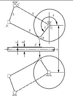
Figure 2 Schematic diagram of the crank flying shear mechanism
Autodesk's Autodesk Inventor Professional 11 (hereafter referred to as AIP11) can solve the problem of design size structure, and its embedded motion simulation and finite element analysis module provides a good solution to the above problems, allowing designers to In a CAD software, from product concept design to motion analysis, to the release of relevant calculation reports can be easily completed.
How to analyze the kinematics performance of the start-stop crank flying shear mechanism in AIP11?
Using the convenient and quick styling function of AIP11, the crank, the clipper frame and the scissors are designed according to the requirements. For the conventional mechanism model, the stretching and rotation commands in AIP11 can be basically completed. Enter the pressure angle, helix angle, and center distance in the Design Accelerator to become the coefficient solution (see Figure 3). In the component environment, the parts are assembled according to actual requirements, so that the required schedules in the drawing can be generated in the future. Verifying the design dimensions and ensuring that the components are free of interference in the actual assembly position is not a difficult task.
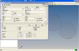
Figure 3 uses the design accelerator to generate the required gears
Now install the assembled start-stop crank flying shears, change the assembly relationship in this model, make all the parts into the same level assembly tree, and simplify the appropriate structure to make it a mechanical model. (See Figure 4)
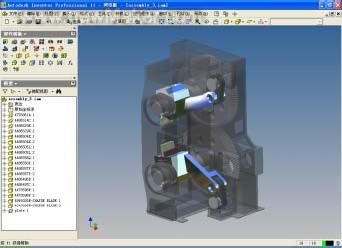
Figure 4 simplified mechanical model
Entering the simulation environment, the first command in the toolbar is used to add various motion connection conditions including hinges to the parts (see Figure 5). We can also use the "inherit assembly" function to align the assembly. The assembly conditions such as insertion are automatically converted into the connection conditions in the motion simulation. Note that the angle constraints in the assembly, excessive and motion constraints are not convertible.
Figure 5 Insert connection function
Next page
Decorative Light,Outdoor Decorative Lamp,LED Decorative Lamp,Outdoor Square Lights
Tianjin Jinji Optoelectronic Technology Co., Ltd. , https://www.tjjjgd.com