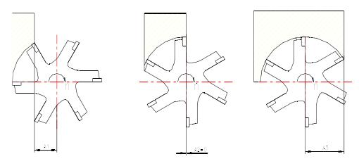
In Figure a, the cutter axis is completely outside the width of the workpiece and the impact force at the time of the cut is received by the outermost tip of the blade, which means that the initial impact load is absorbed by the most sensitive part of the tool. Finally, the milling cutter also leaves the workpiece with the tip of the tool, that is to say, the cutting edge is cut from the beginning to the cutting edge, and the cutting force acts on the outermost cutting edge until the impact force is unloaded. In Figure b, the center line of the milling cutter is just on the edge line of the workpiece. When the chip thickness reaches the maximum, the blade is out of the cutting, and the impact load is maximized when cutting in and out. In Fig. c, the axis of the milling cutter is located within the width of the workpiece. The initial impact load when cutting is carried along the cutting edge from the farthest point of the most sensitive tool tip, and the blade exits the cutting smoothly when the blade is retracted.

For each blade, the way the cutting edge leaves the workpiece when exiting the cutting is important. The material remaining near the retraction may reduce the blade clearance somewhat. When the chips are detached from the workpiece, an instantaneous tensile force is generated along the rake face of the blade and burrs are often generated on the workpiece. This tensile force jeopardizes the safety of the cutting edge in hazardous situations.
When the milling cutter axis and the workpiece edge line coincide or approach the edge line of the workpiece (Figure b), the situation will be severe. A summary of achieving better milling:
1 Check the power and stiffness of the machine to ensure that the required cutter diameter can be used on the machine.
2 The overhang of the tool on the spindle is as short as possible. The influence of the axis of the milling cutter and the position of the workpiece on the impact load 3 uses the correct milling pitch suitable for the process to ensure that there are not too many blades at the same time to cause vibration when meshing with the workpiece, and on the other hand milling narrow workpieces Or when milling the cavity, make sure that there is enough blade and workpiece engagement.
4 Ensure that the feed per blade is used to achieve the correct cutting results when the chips are thick enough to reduce tool wear. The indexable insert with positive rake groove shape provides smooth cutting results and lowest power.
5 Select the diameter of the milling cutter suitable for the width of the workpiece.
6 Select the correct lead angle.
7 Place the milling cutter correctly.
8 Use cutting fluid only when necessary.
9 Follow the rules for tool maintenance and repair and monitor tool wear.
Previous page next page
Freight Elevator,Heavy Duty Cargo Lift,Freight Lift Elevator,Vertical Cargo Lifts
APSL ELEVATOR TECHNOLOGY(SUZHOU) CO.,LTD. , https://www.fujiapsl.com