Foreword
The rigidity of the modern machine Tool spindle component is the main indicator reflecting the structural performance of the spindle component. It comprehensively reflects the deformation of the spindle and the bearing, which is directly related to the machining accuracy of the machine tool. The high-speed spindle is one of the key components of the machine tool. Therefore, when designing the spindle assembly of the high-precision CNC machine tool, it should meet the requirements of high rigidity. The stiffness of the main shaft member is usually measured by the displacement generated in the direction of the force by applying a certain force to the front end of the main shaft. This is called the displacement of the end "deflection" and is an important parameter for designing the spindle component. The allowable deflection has a decisive influence on the stiffness of the spindle component, so it determines the performance of the machine tool.
First, the source of [y]=0.0002L
At present, there is no uniform provision for the allowable value of the stiffness of the spindle components. Most of them take the displacement of the end of the main shaft, the rotation angle of the front bearing, the rotation angle of the gear meshing and the maximum cutting width without flutter, and some empirical data and formulas are often used for control. Among them, in the displacement of the spindle end, the following content is often used to control [2][3]:
1. The displacement of the end of the spindle of the finishing machine does not exceed one third of the allowable radial runout of the spindle;
2. The spindle end deflection [y] = 0.0002L for general machine tools.
The permissible deflection is widely used in China. At present, the empirical formula is also cited in the textbooks of various schools. As we all know, most of the teaching materials in China are from the former Soviet Union. Almost all of them use the authoritative work of the former Soviet Union's machine tool research, Lishetov and Achelcon, to discuss the allowable deflection of the shaft and the spindle in the early years.
The literature [5] proposed: "Most of the axes in the machine tool (this section does not include the main shaft), the ratio of the maximum deflection to the length between the bearings is in the range of 0.0001---0.0005. Generally not more than 0.0002."
Also in the literature [6]: "The general criteria for determining the allowable deflection of the machine tool spindle and shaft have not been studied. Therefore, in the machine tool builder, the test data that can be applied to the machine tool without causing waste is currently used. Widely used data: The maximum deflection of the spindle or shaft is 0.0002 times the distance between the shaft seats.†As can be seen from the above two documents, they do not specify the end deflection, and the two authoritative discussions involve different scopes. Shetoff stated that the spindle was not included, and that Achelcon stated that it included the main shaft.
Some textbooks in China, such as the literature [1] introduced: "Some factories believe that under the rated load, the maximum deflection y max of the main shaft must not exceed 0.0002L." Also available in the literature [2], [3], [7]: "Spindle There is no uniform standard for the allowable value of the end deflection y. Some data are recommended. For general machine tools, the maximum displacement of the spindle end is required to be y max ≤ 0.0002L or the avoidance specification is used: “At present, there is no uniform stiffness of the spindle component. Standard." There is also the 2006 version of the "Mechanical Design Manual" [8] Table 5-1-4, it is recommended that "metal Cutting Machine spindle y maxP = 0.0002L" can be seen, the latter is to indicate the end of the spindle deflection, while the former Not specified. But it can be judged from the arguments of Archer Kang.
Second, the typical machine tool deflection calculation
Since there are many types of spindles for machine tools, in order to select a typical example of structure and performance to illustrate the problem, the calculation of the spindle end deflection of several typical lathes is taken as an example.
In the calculation process, according to the different forms of support, it is divided into three calculation forms, and the upper computer (the calculation source program is slightly omitted):
1. Two support structure forms: shown in Figure 1.
The spindle end deflection is:
y=P[a 3 /(3EJ)+La 2 /(3EJ)+(1+a/L) 2 /C 1 +(a 2 /L 2 )/C 2 ]
Next page
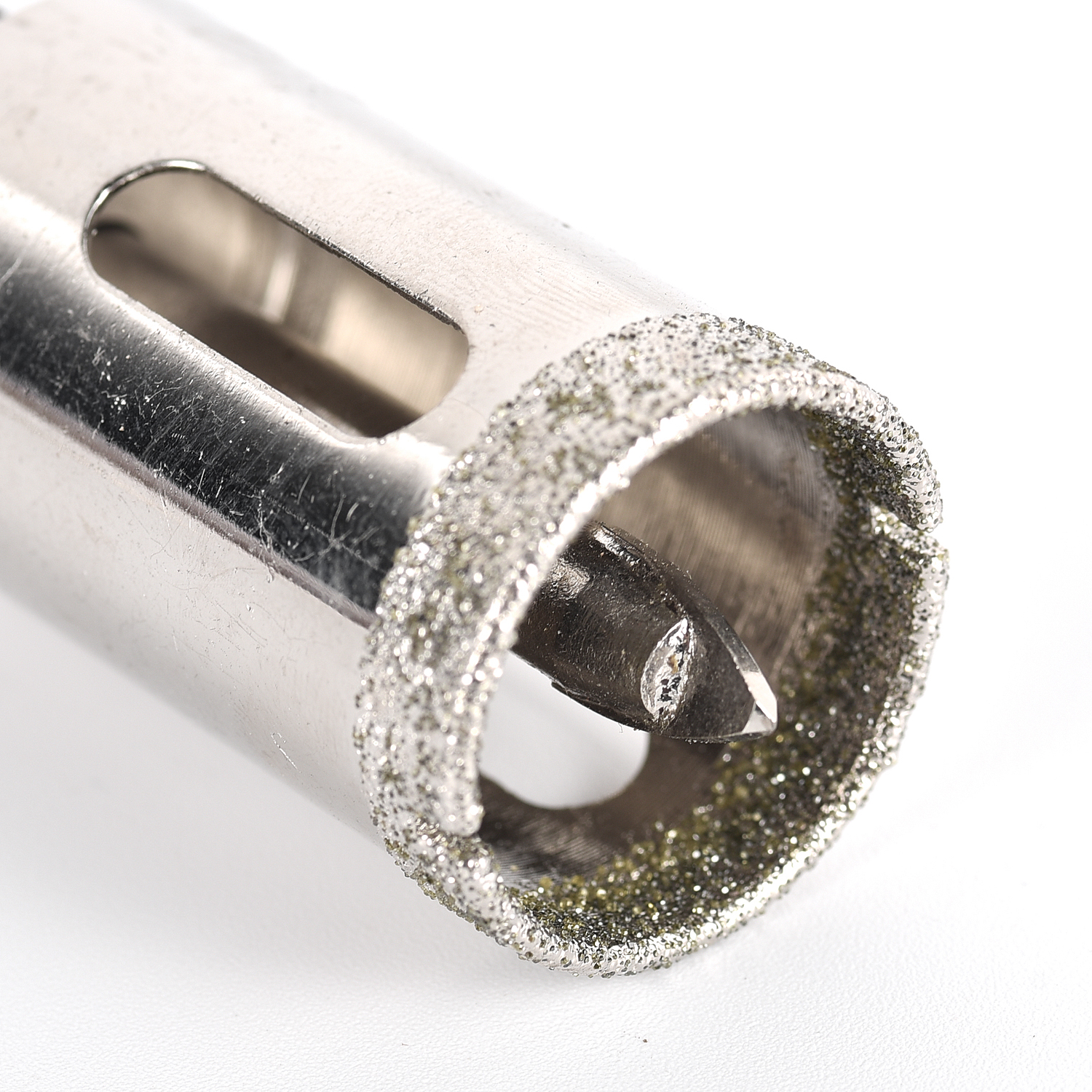
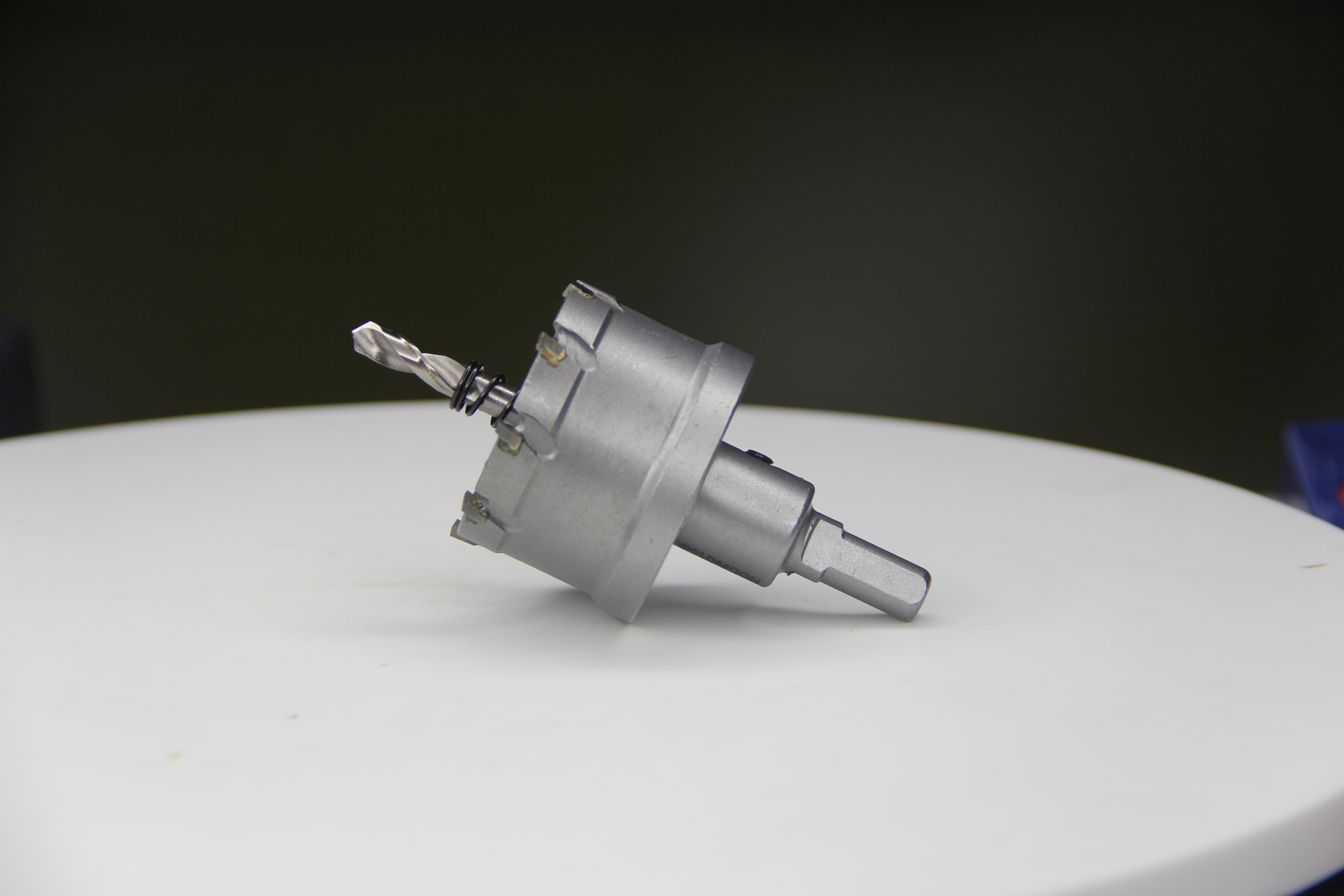
The hole saw, also known as the hole saw or hole saw, refers to a special circular saw in the processing of circular holes in modern industry or engineering. It is simple and flexible to operate, convenient to carry, safe and widely used. The hole opener (cutter) is installed on the ordinary electric drill, and it is convenient to cut round holes, square holes, triangular holes, straight lines and curves on the plane and sphere of various plates such as copper, iron, stainless steel and plexiglass.


Hole Saw,Hole Saw Kit,Hole Saw Cutter,Tile Hole Saw
Behappy Crafts (suzhou)Co.,Ltd , https://www.jshaoyue.com