Surface modeling is an indispensable advanced tool in product design, and a skill that 3D CAD designers must master, but for beginners, it is not easy to find an easy-to-start surface modeling example. Therefore, in November's 3D CAD quick tutorial, Xiaobian chose to use the iron shape that is more suitable for learning surface modeling as an example, so that more students who are just in contact with 3D CAD design can understand the operation of surface modeling. So this small series still uses Zhongwang 3D, which has the advantage of original hybrid modeling, as the example software. At the same time, this tutorial also involves many basic 3D CAD software command applications, which can help students improve the proficiency of 3D CAD software. Interested friends can also download the 3D CAD drawings of the electric iron for free after learning, and learn more with less.

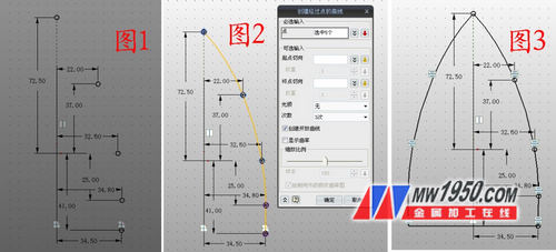
1. Insert sketch 1 on the xy plane, draw 5 points according to the logo of Figure 1, click through the point to draw the curve, connect each point in turn, as shown in Figure 2, click on the mirror, copy this curve along the Y-axis, and then Closed, as shown in Figure 3.
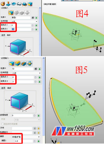
2. After exiting the sketch, click Stretch, and the outline selects Sketch 1, and the stretch distance is 2, as shown in Figure 4. Click on the stretch again and select the upper surface of the shape of Figure 4. The stretching distance is 3. Note that the offset option selects the "shrink/expansion" offset to -1.8, as shown in Figure 5.
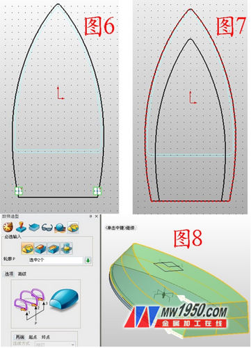
3. Insert the XY datums 1 and 2 in turn, and the offset distances are 4 and 30 respectively. Insert the sketches 2 and 3 on the datums 1 and 2, respectively, and draw the graphs shown in Figures 6 and 7. (Note: Draw Figure 6 Tips, first set the edge of the shape as a reference curve, right click on the curve to select "switch type", turn into a solid type, so that it is more accurate and convenient, then extend the bottom of the curve; draw the skill of Figure 7, first put The part shown is set as the reference curve, then click on the offset curve, offset the reference line inward by a certain distance, then move it down, trim the part that grows at the bottom, and then close it.) Click Stakeout and select Sketch 2, 3 in turn, as shown in Figure 8.
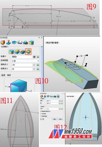
4. Insert the sketch 4 on the YZ plane, draw the graph shown in Figure 9, exit the sketch, click the stretch-intersection operation, the outline is the sketch 4, the parameters are as shown in Figure 10, and the sketch 5 is inserted in the ZY plane, as shown in Figure 11. Curve, exit the sketch, click on the wireframe - the projection curve, the curve is sketch 5, the surface is the upper surface of the shape, as shown in Figure 12.
5. Insert sketch 6 on the XZ plane, select “Curve intersection†on the reference curve, draw the line segment as shown in Figure 13, and then mirror this line segment to the other side. Exit the sketch, click the drive line to stake out, the drive line selects the projected curve, and the outline is sketch 6, as shown in Figure 14 (note that the sides are staked in sequence, not once). Click to trim, the base is the main shape, the trimming surface is the drive line stakeout curve, and the sides are trimmed in turn. Note that the tick is placed before the “extended trimming surfaceâ€, otherwise the trimming may not be completed. Also pay attention to the pointing of the white arrow. The direction is the part to be retained. If the direction is not correct, you need to tick the "retaining opposite side", as shown in Figure 15. Click on the shell, the shell is shelled, the thickness is -1, the open surface is the bottom surface, and the edges are rounded, as shown in Figure 16.
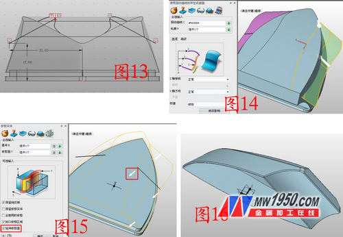
6. Insert the sketch 7 on the YZ plane and draw the curve shown in Figure 17. For the drawing method, refer to the method in step 3. After exiting the sketch, stretch the sketch 7, as shown in Figure 18. Insert the sketch 8 on the XY plane and draw the graph separately. , the curve shown in 20.
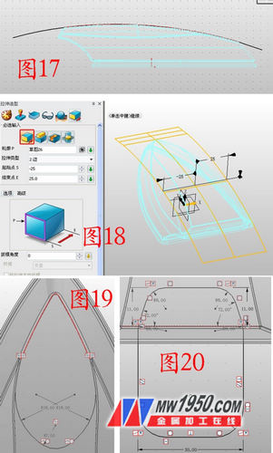
7. Click on the projection curve, select the sketch 8 in the curve, and select the surface to be stretched in step 6. As shown in Fig. 21, the projected curves are named as curves 5 and 9, and the hidden surfaces are respectively hidden. In the YZ surface illustration sketch 9, the reference curve selects "curve intersection", select the projected curve, and draw two curves as shown in Fig. 22, respectively named as curves 1, 3, as long as the approximate shape is similar.

8. Insert the reference planes 3, 4, and 5 respectively, and sequentially shift the distances to -0.5, 19.5, and 42. As shown in Fig. 23, insert the sketch 10 on the reference plane 4, and draw the ellipse shown in Fig. 24. Note the selection of the reference curve. (When selecting the center point, you can right click the mouse to select between two points, click two reference points respectively, the percentage is 50%, and the long axis is 22). According to this method, a sketch is inserted on the reference planes 3, 5, and two ellipsees are drawn, and the long axes are 15, 18 respectively. As shown in Fig. 25, the three curves are named as curves 6, 7, and 8, respectively. Click on the wireframe - draw the curve by point, as shown in Figure 26, click on the link to form a curve (the two endpoints of the curve do not have to be very precise, but must be on the curve, the middle of the long axis of the ellipse), and the two curves Named as curves 2 and 4 respectively.
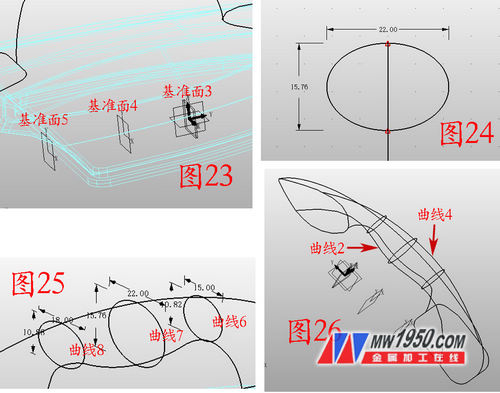
9. Click on the surface - U/V surface. The U curve selects curves 1, 2, 3, and 4 in turn. The V curve selects curves 5, 6, 7, 8, and 9, in turn, as shown in Figure 27, click on the reverse surface direction. , invert the surface, click on the FEM surface, and close the surface, as shown in Figure 28. Insert the sketch 11 on the YZ plane and draw the graph shown in Figure 29. As long as the shape is roughly shaped, exit the sketch, click the stretch-subtraction operation, stretch the sketch 11, and round the edges, as shown in Figure 30.
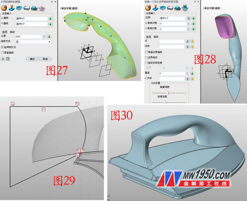
At this point, the outer body portion of the electric iron is completed. Through this surface modeling tutorial, students can master the modeling of 3D CAD surface modeling as soon as possible, and combine the 3D more free surface and physical interaction hybrid modeling technology. Beginners can reduce familiarity. At the operational level, more attention is paid to the design itself. December's 3D CAD quick tutorial preview, Xiao Bian will hit the iron hot, share the design of the electric iron parts for everyone!
Zhongwang 3D 3D CAD/CAM software
Download Zhongwang official website for free .
Zhongwang 3D is the preferred brand of 3D CAD/CAM recommended by the Ministry of Industry and Information Technology for military enterprises. It provides cost-effective 3D CAD/CAM solutions for enterprises, modeling, mold, assembly, reverse engineering, sheet metal, 2-5 axis processing and other functional modules. Everything is available. Efficiently compatible with other 3D CAD software, easy to learn and use, integrated rich parts library, new learning tutorials and free download of massive quality 3D CAD drawings, etc., making it easier for you to master 3D design and machining programming. Download the latest version now and apply for free 3D CAD/CAM & 3D printing technology training.
Cheap Measuring Tape,Steel Blade Tape Measure,Woodworking Measure Tape,Easy Read Measuring Tools
Yucheng Weisite Measuring Tools Co., Ltd , https://www.wsttool.com