Deep hole processing technology has been widely used in the defense industry, petroleum mining, aerospace, machine tools, automotive and other industries, and due to its high efficiency, high precision and other advantages, deep hole processing technology is also in the shallow hole processing of some parts. In the application. In recent years, deep hole processing technology has developed rapidly. China's machinery manufacturing industry has made great progress in the research of deep hole processing technology, such as deep hole vibration drilling combined with deep hole drilling and low frequency vibration cutting. Technology; spray suction system, single-tube chip discharge drill (SED) system, gun drilling system, BTA drilling system, deep hole nesting drilling system, etc. also have corresponding research and innovation. For many years, our company has been committed to the research of deep hole machining technology. In the design and manufacture of deep hole machine tools and drilling and boring tools, we have made satisfactory results in the improvement of deep hole drilling technology and chip removal system. The development of the small deep hole processing technology for internal chip removal and the results we have obtained are described below.
Development status of small deep hole processing technology at home and abroad
According to the information retrieval, the world's deep hole drilling technology using external chip removal (such as gun drill) can drill a small aperture of f2mm. The inner hole chip deep hole drilling has a small diameter of less than f16mm, and most of them still use the traditional BTA drilling system. Since the structure of the gun drill is asymmetric, the center of mass deviates from the central axis, which brings certain difficulties to manufacturing and re-grinding, and also increases the cost.
In addition, its structural rigidity and torsional strength are low (the torsional stiffness of a circular drill pipe of the same diameter is 2.3 times that of a gun drill), which reduces the drilling speed used and the feed amount is small. With a single-tube internal discharge drill (SED) drilling system, the diameter of the drilled small deep hole can be as small as f3.7mm. The SED technology used in our process has carried out small deep hole drilling with apertures (mm) f16, f12, f10, f8, f7.62, f5.7, f3.7. The drilling process is smooth and the chip removal is smooth. The dimensional accuracy and the surface roughness of the hole wall are satisfactory, and in the above-mentioned aperture range, the drilling of the small deep hole can be completely replaced by the gun drill. Due to its good rigidity, the feed rate and drilling speed can be increased, and the production efficiency, drilling quality and economic benefits are improved, showing a certain technical advantage.
Difficulties and countermeasures of small deep hole machining technology <br>Deep hole drilling process is quite difficult. The difficulty of small deep hole drilling in internal chip removal is more prominent, mainly in the following aspects:

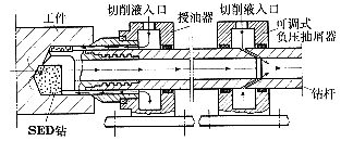
Figure 1 SED deep hole drilling system

Figure 2 Threaded deep hole cutter
Difficulties in chip removal
The chips in the small deep hole drilling of the inner chip are discharged through the chip removal passage in the drill pipe. The smaller the hole diameter, the more difficult it is to remove the chips. For example, to drill a deep hole of f8mm, the outer diameter of the drill pipe is f5.2 mm, the inner diameter of the drill pipe is only f4 ~ 4.2 mm, and the length of the drill pipe is generally 500 ~ 1500 mm. Therefore, it is not uncommon to have chipping during the drilling process. In order to make the chip removal smooth, it is very important to design a reasonable chip breaking and chip breaking table on the cutting edge of the drill to ensure reliable chip breaking. However, the feed of small deep holes is small, and it is impossible to achieve C-shaped chip breaking for some tough materials. The cuttings are often soft and small, and the cutting fluid pressure is generated as cooling and flushing chips during drilling. When the fluctuation or pressure drops, the chips are instantaneously stagnant, folded and clogged, which leads to damage of the cutting edge and twisting of the drill pipe. In order to completely solve this problem, measures can be taken from both chip breaking and chip removal. The most effective method of chip breaking is to use the vibration chip breaking technology to stably obtain the required cutting shape.
Increasing the chip removing force of the cutting fluid on the cuttings is the characteristic of the SED drilling system. As shown in Figure 1, the high-pressure cutting fluid enters the oil feeder, lubricates the cooling drilling zone and the cutter, and takes 3MPa~4.5 MPa. The pressure forces the chips into the chip evacuation passage and pushes the chips out; the other cutting fluid enters the adjustable negative pressure chip extracting device to form a negative pressure, which generates suction to the chips and sucks out the chips. The chips can be discharged smoothly under the dual action of pushing and sucking. Practice has proved that even if the drill cuttings are strip-shaped and continue to be continuous from the beginning of drilling to the end of processing, the chip removal can be smooth and smooth.
The drill pipe is not rigid enough. The deep hole drilling drill pipe is thin and long. The small deep hole drilling drill pipe is slender and its rigidity is very low. Therefore, when designing the small deep hole tool, the tool should be improved as much as possible. The overall stiffness of the drill bit and the drill pipe). In the traditional design, the drill pipe and the drill bit are connected by a square thread (see Figure 2). This is to cut the square thread on the drill pipe with a thin pipe wall, which will inevitably reduce the strength and rigidity of the elongated drill pipe.
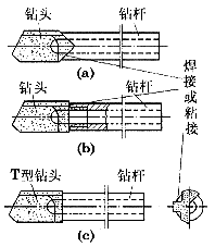
For drilling a deep hole of f5.7mm, the outer diameter of the drill pipe can only be f4mm. The depth of a square thread is 0.25mm when the wall thickness is less than 1mm. The strength and rigidity of the threaded joint are greatly reduced. During drilling, The drill pipe is often twisted at the threaded joint. That is, the small feed rate is used to reduce the drilling torque, and the twisting accident cannot be prevented. In order to solve this problem, the three methods shown in FIG. 3 can be used for the connection of the drill pipe and the drill bit for drilling the hole having an aperture of less than 12 mm.

Figure 3 welding (bonding) tool
Figure 3a shows the drill bit and the drill pipe as a 90° nipple, which is joined to the drill bit by low temperature silver welding (sometimes also by brazing) or bonding. Fig. 3b shows that the diameter of the drill shank of the drill bit is small, and the diameter of the drill pipe joint is enlarged and integrated with the drill shank, and then welded at a joint with low temperature or by bonding. In Fig. 3c, the cemented carbide insert is made into a "T" type end face, and a "T" groove is correspondingly milled on the drill pipe, and the insert is inserted and fixed. These three methods have been tested several times, and the strength and rigidity of the joints of the square teeth are better. The feed amount during deep hole drilling can be appropriately increased, and the production efficiency is also improved accordingly.
Manufacturing difficulties
If the drill pipe and the drill bit are connected by a traditional thread, the internal thread of the square tooth should be drilled in the hole of the drill pipe of the small deep hole. The thread turning tool is smaller than the inner diameter of the drill pipe, and the blade must be sharply ground. The size of the blade; the pitch of the square thread is large, and it is not intuitive to process when the car is made, and the operation is very difficult. The manufacture of the drill bit is more difficult. In addition to turning the square thread on the shank, a groove for the welding of the cemented carbide bar and the blade and a chip evacuation passage are milled on the small diameter cutter head. After that, the high-temperature welding of the cemented carbide bar, the blade and the cutter body may cause overheating and deformation. Therefore, it is quite technically difficult to manufacture qualified small deep hole drilling tools in terms of process and operation.
With the measures shown in Figure 3, the manufacturing process is relatively simple. The manufacture of the drill bit part is all changed to a powder metallurgy hard alloy small drill bit. As long as a one-time investment is made to produce a mold of a powder metallurgical small drill bit, the blank of the cemented carbide drill bit for drilling a small deep hole can be obtained, and the process is simple. Moreover, the regrindability of the tool is good, and the normal use can be re-grinded 3 to 4 times, which generally reduces the tool cost. We call this new structure of small deep hole cutters a single-tube internal chip evacuation drill.
The cutting speed of small deep hole drilling and the cutting speed of general alloy steel used in machine tool cutting with carbide machining tools are at least 70m/min, while the small deep hole machining machine produced in China in the past has a maximum speed of 2500r/min. It is impossible to carry out stepless speed change and stepless feed, obviously it can not meet the technical requirements of small deep hole drilling. In 1992, we designed and organized the ZK2116×2 CNC double-axis deep hole drilling machine (internal and external chip removal) and ZK2112 CNC deep hole drilling machine with the maximum speed of 6000~10 000 r/min. In particular, the ZK2112 CNC drilling machine has three kinds of motion modes for deep hole drilling: 1) workpiece rotation, tool feed; 2) workpiece rotation, tool rotation and feed; 3) workpiece does not move, tool rotates and feeds. This machine also has a vacuum suction device. The development of this new machine tool has broadened the scope of deep hole machining and also raised the deep hole machining technology to a new level.
The application of GT and CAD technology in deep hole machining The group technology (GT) and computer aided design (CAD) developed by modern computer tools have greatly promoted the advancement of machining technology. In the advancement and development of small deep hole processing technology, there have been many reports of successful use of GT and CAD. For example, the deep hole cutter and its accessories use GT technology to establish a classification and coding system, and on the basis of this, carry out the development of the corresponding CAD system software, which lays a foundation for the serialization and standardization of deep hole cutters. At the same time, the development and application of CAD software enables the design process of deep hole drilling to be realized by computer, which not only greatly improves the design speed, but also avoids and reduces errors in the design. Our Institute of Technology has also achieved good results in the use of GT and CAD technology. It has successfully developed a CAD system for designing deep-hole tools. It can use CAD systems for gun drills, single-tube internal chip discharge drills, and machines. Deep hole machining tools such as deep hole boring tools are designed and selected.
Screwdriver,2M Tape Measure,Cute Measuring Tape,Yellow Measuring Tape
SHANGQIU CHAOYUE MEASURING TOOLS CO., LTD , https://www.equipmentool.com