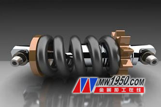
Many beginners who want to quickly master 3D CAD modeling are suffering from some case tutorials that are too complicated. Xiaobian will introduce the requirements for beginners every month, and provide case tutorials that can understand the basic operations of 3D CAD modeling in a short time. In May, the teaching case shock absorbers are used in various industries. There are more 3D CAD modeling commands and more detailed parameter settings, but the overall difficulty is not great. This is for the quick start of 3D CAD design. For beginners, it is a very good case tutorial. Today, choose Zhongwang 3D as the teaching software , which is easy to learn and use, and can help you understand the 3D CAD design more easily. Next is the 3D modeling process of the shock absorber.
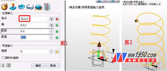
First, make the spring part. This part is relatively difficult. Because the distance between the middle part of the spring is large and the distance between the two parts is small, how can we achieve seamless and continuous connection? Zhongwang 3D2012 can easily solve this problem. Click on the wireframe - the spiral, the parameters are shown in Figure 1, and the starting point is on the X axis. Click on the wireframe - select the spiral by tapping/breaking the curve, select the point to be broken at the opposite end of the spiral, and break the spiral into 3, as shown in Figure 2.
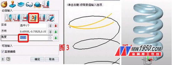
Click on the shape - move - rotate around the direction, select the top curve, the direction is shown in Figure 3 (put the mouse to the direction of the curve to show the direction arrow), rotate -12 degrees. For the same reason, rotate the bottom curve at an angle of 12 degrees.
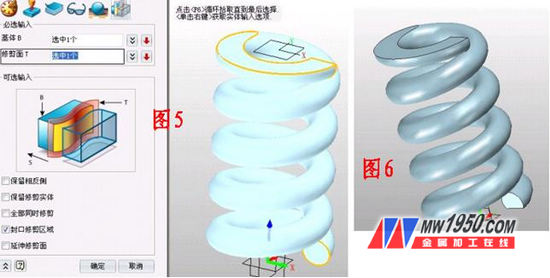
Click on the wireframe - connect the curves and connect the three segments to the entire curve. Click on the shape - rod sweep, diameter 18, as shown in Figure 4. Create two XY datums, offset 186 and 12 respectively, click on the shape-trim, the parameters are shown in Figure 5. Note that the selection of the part is retained. The effect is shown in Figure 6.
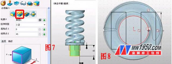
Insert the XY plane into the sketch, draw a circle with a radius of 39 from the origin, exit the sketch and stretch, and the start and end points are 8 and -2 respectively. Insert a sketch on the bottom surface of the extruded cylinder, draw a circle with a radius of 20, and stretch. The effect is shown in Figure 7.
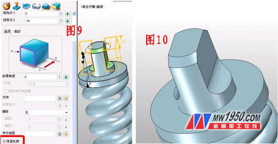
Insert a sketch on the XY plane and draw two rectangles that are symmetric in the vertical direction, 20 apart, as shown in Figure 8. First chamfer the edge of the small cylinder with a distance of 5. Select Stretch - Subtract operation, stretch two rectangular sketches, the parameters are shown in Figure 9. Note that the front of the contour will be checked and left for later use. Then round the position as shown in the figure, the radius is 10, the effect is shown in Figure 10.
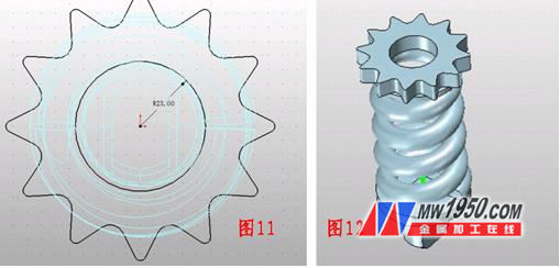
Insert a sketch on the XY plane, draw the graph shown in Figure 11, exit, point stretch - base, note, when you select the starting point, if you don't remember the distance of the plane on the spring from the origin, there is a simple method, right click the mouse Select the "target point", place the point on the upper plane of the spring, click to display the data, this method is very simple, and the application is also very extensive. The shape with a thickness of 20 is stretched, and the effect is shown in Fig. 12.
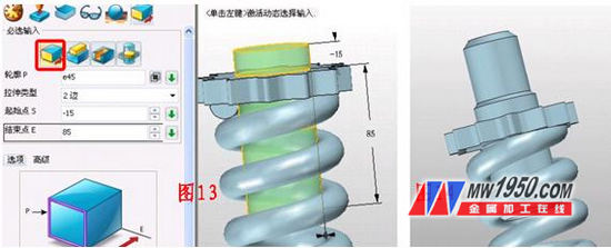
Click Stretch - Base, the outline selects the upper edge of the hole. The data is shown in Figure 13. The upper and lower edges of the stretched cylinder are chamfered at a distance of 3. Click on the stretch again - add operation, the contour selects the upper surface of the cylinder, stretches the cylinder with a height of 45, and chamfers the distance to 5, the effect is shown in Figure 14.
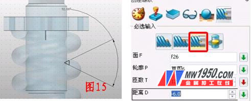
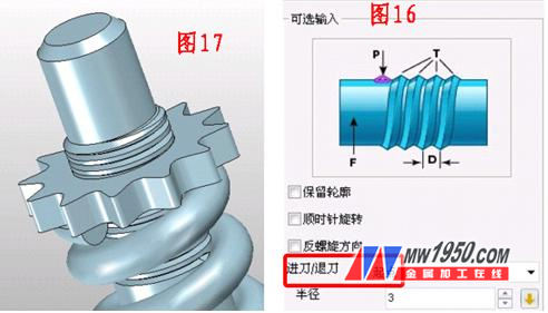
Insert a sketch on the YZ plane to draw the triangle as shown in Figure 15, click on the shape - thread - subtraction, parameters and effects as shown in Figure 16. The effect is shown in Figure 17.
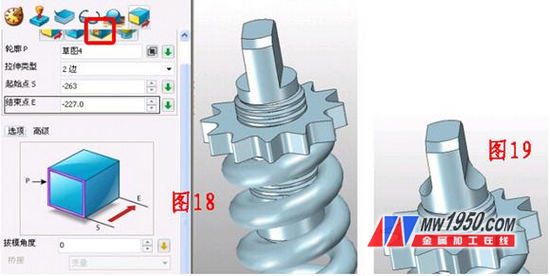
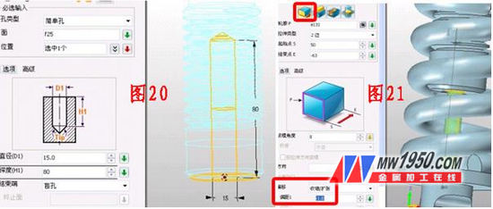
Stretch the sketches of the two rectangles before again, as shown in Figure 18. Note that this time remove the check mark from the "Retain Outline". The portion shown in Fig. 19 is rounded and has a radius of 10. Click on the shape-hole and punch the hole in the center of the lower surface of the cylinder shown in Figure 20. The parameters are as shown in the figure. Click on the stretch - the base, the outline is the edge of the hole, pay attention to offset a certain distance, and the tensile data is shown in Figure 21.
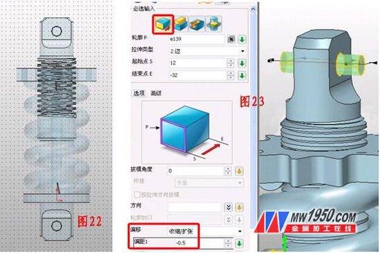
Insert a sketch on the YZ plane and draw a circle with a radius of 6 as shown in Figure 22. After exiting the sketch, the stretch is subtracted to form two holes. Click Stretch - the base, the outline is the edge of the hole, the data is shown in Figure 23, and a cylinder is drawn out, paying attention to the setting of the offset data.
Click on Stretch - Base, and stretch out a boss as shown in Figure 24. The data is as shown in the figure. Then draw a circle with the edge of the hole as the outline, as shown in Figure 25, and then fill the circle. Insert a sketch on the outer surface of the boss, draw a regular hexagon and stretch and subtract it, as shown in Figure 26. Click on the mirror to copy the boss and the ring to the XZ plane image, as shown in Figure 27.
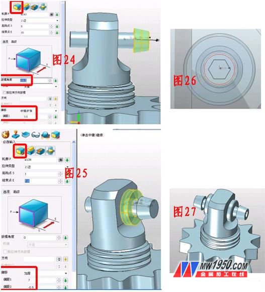
Click Copy - Copy in the direction, copy the distance between the two bosses, the ring and the axis shown in Figure 27 by 230 in the negative direction of the Z axis. After the model is finished, click on the visual style - face attribute. Color the model.
After the operation, is there any experience in modeling 3D CAD? Interested friends can come to Zhongwang 3D official website to download Zhongwang 3D (), and now also provide free 3D CAD drawing download of shock absorbers, in the monthly 3D technical exchange forum A practice can be downloaded: http://!
For over 100 years, AKH Die Casting has been dedicated to providing companies with superior die casting and tooling, along with metal finishinig and CNC MACHINING AND Grab Bar through state of the art machinery and processes. Specializing in ALUIMNUM and ZINC ALLOYS, engineers and production staff will develop a high pressure die casting process that will produce your parts economically and with reliable quality
NINGBO AIKEHAN continues to invest in state of the art machines and technology to provide process consistency, precision, and reduced labor. Combining automated process monitoring and an expert staff of process technicians means we can quickly detect process issues and correct for out of control variables.
Utilizing a licensed vacuum system, we improve the surface finish and integrity of our castings and molds, ensuring our clients receive only the highest quality work from the Premier team.
Advanced Die Casting Technology
.
Aluminum Die Casting Parts,Aluminum Led Housing,Aluminum Heatsink Profile,Extruded Aluminum Heatsink
NINGBO AIKEHAN METAL PRODUCT CO.,LTD , http://www.diecastingsupplier.com