Building a virtual simulation platform
One indicator of virtual simulation processing technology is that the virtual simulation environment and system can realistically reflect real processing. Therefore, in the process of constructing the virtual machine tool environment, it is necessary to carefully collect the relevant technical data and appearance data of the physical machine tool, and clarify the geometric motion relationship between the motion axes of the machine tool to ensure that the constructed virtual machine tool environment is consistent with the physical machine tool environment.
1 virtual simulation
The Vericut software was selected and the CimcoEdit software was assisted as a platform for the process simulation system to simulate the overall impeller.
(1) Vericut software.
Vericut is a CNC machine tool machining simulation and optimization software developed by CGTech in the United States. It has been widely used in the processing of complex parts and high-precision parts (such as turbomachine parts) since its inception in 1988. . By preparing to simulate the entire machining process and verifying the machining program, Vericut avoids machine collisions and interference, optimizes the program, and improves production efficiency and surface quality.
(2) CimcoEdit software.
In addition to the more powerful Vericut software, there is a convenient program code encoding viewing software CimcoEdit at two different levels of programmers and operators. It has low requirements on computer hardware environment, is easy to operate and apply, and is suitable for application in manufacturing field. It has practical functions such as numerical control editing function, intelligent comparison of files, 3D simulation of tool path and program statistics.
2UCP800 five-axis machining center simulation platform
The establishment of the process simulation system requires pre-definition or configuration of the machine environment, fixtures, tools, control systems, etc. In order to obtain the machine geometry motion model and related data, it is necessary to analyze and measure the mechanical motion relationship between the machine-related components and the corresponding dimensions ( For example, the geometrical motion relationship between each axis of X, Y, Z, A, and C), the size of the table, the size of the attachment head, and the initial height of the beam from the table.
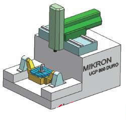
Through the collection, sorting and analysis of the relevant technical data of the machine tool, the UGNX4.0CAD software function was used to construct the 3D model of the UCP800 machine tool with the center of the machine C rotating table as zero point, and the Mikron five-coordinate machine tool model was completed, as shown in Fig. 2.

Wide application of impellers in aerospace and other fields
According to the geometric motion structure of the machine tool shown in Figure 2, in the Vericut software simulation environment, open the "ComponentTree" machine structure tree, and first add the X, Y, Z of the machine tool under the "Base(0,0,0)" node. A and C have a total of 5 moving parts, and then re-layout by dragging according to the linkage relationship between the axes. In order to realize the authenticity of the machine tool simulation, the components of the 3D machine tool constructed by UG are output in the STL format and added to the relevant components of the machine structure tree, and the UCP800 machine structure tree is configured.
For machine tools, the control system is the premise for correctly simulating the machining program and is the interpretation and processing of the machining program instructions. Next, configure the control system for the impeller simulation environment. The CNC control system of the Mikron UCP800 coordinate machine is configured as the Heidenhaini TNC530 system, so select Hei530.ctl in the "Library" directory of the Vericu software.
Vericut software itself has the basic functions of the control system, but for each physical machine tool, there will be some special instructions. For the special instructions that are not available in these control system files, it must be redeveloped through macro commands and scripts. Programs, etc. to achieve special customization.
3 tool magazine environment
The establishment of the tool magazine mainly includes the establishment of tools, tool holders and blades, as well as the definition of tools, tool drive points and clamping points. Taking the machining tool environment of the overall impeller as an example, this paper constructs a relative tool magazine for the workpiece. In order to ensure the authenticity of the tool data, the actual measurement of the tool holder of the UCP800 machine tool is required. According to the measurement data, the tool holder contour is created by means of the UGCAD function.
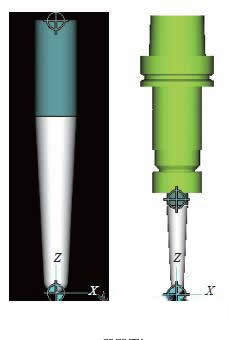
Then open Vericut's ToolManager dialog box, right-click in the left area, pop up the shortcut menu related to "Tool Management", and follow the prompts to create "Mill Milling Cutter". Set "ToolID" to "1" tool and the tool used to machine the impeller is a taper tool, so select the subtype. In order to reflect the actual tool state, it is necessary to assemble the tool holder created in the front.
First, export the shank contour created by UGCAD in DWG/DXF format, and then create a new tool according to the above steps. Here, it is named “4†knife. The difference from the creation of “1†knife is that its component type is "Holder's handle". The next step is to assemble the shank for the "1" knives. The "1" tool before and after assembly is shown in Figure 3. According to the above ideas, create the "2" knife and the "3" knife, and finally complete the tool library file.

Wide application of impellers in aerospace and other fields
| Previous page | 1 | 2 | 3 | Next page |
LED Downlight
LED downlight ,with LEDER technology's smooth design is an enhanced and modernized retrofit light. Using a secure and reliable installation method, this light is compatible with housing that features interior spring bracket holders.
Built with steady dimmable technology, and compatible with most modern dimmers including wireless systems. LED Downlight is an especially good choice for anyone looking for a lamp which is elegant in an understated way. If you want an LED Downlight that discreetly keeps itself out of the way, yet looks great once you actually pay attention to it, you have definitely come to the right place. This LED Downlight will do its job very well.
Features:
• Grace design
• Easy to install
• Excellent power saving
• Suitable for operation at low temperature
• Color temperature :3000K-6000K
• Body color can be customized as RAL Code
• Type of protection: IP20 / IP65 (Some models)
• Warranty: 3 ~ 5 years
Our Downlight is compatible with dimmer switches, so you can always get just the right light for dinner or game night. Bring effortless light into your kitchen, bathroom, or living room with this.
We have rich production experience in lighting.Except LED Downlight , we also offered other product in Indoor Lighting .Such as :
LED Panel Light , Track Light , Linear Light ,Wall Light , LED Strip Light , LED Tube Light , Cabinet Light , LED Bulb , LED Ceiling Light as so on .
Recessed Downlight,LED Recessed Downlight,Halo Ultra Thin Downlight,Surface Mounted Downlight
JIANGMEN LEDERLIGHT LIGHTING Co.,LTD , https://www.lederlight.com